
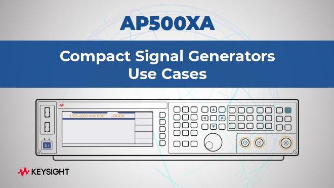
We are excited to share three new RF use cases with you.
These use cases provide application-ready examples to demonstrate how Compact Signal Generators support everyday RF validation and troubleshooting in ways that drive qualified interest and sales.
How to Perform Intermodulation Testing
Accurately measuring intermodulation distortion (IMD) requires generating two or more clean, continuous-wave tones at precise frequencies and equal power levels to reveal an amplifier’s nonlinear response. Traditional test setups using independent signal generators often struggle to maintain balanced tones and spectral purity, as oscillator variations, harmonics, and non-harmonic spurs can introduce artifacts and uneven power at the combiner. These inconsistencies degrade the accuracy and repeatability of IMD measurements, making repeatable testing difficult, particularly in radio and wireless communications, where adjacent-channel interference can limit performance.
An advanced signal generator with superior phase noise and a wide calibrated output power range produces precise two-tone signals for reliable IMD and third-order intercept modulation testing. This approach yields stable, repeatable third-order products essential for accurate nonlinearity characterization, design validation, and manufacturing test, enabling engineers to confidently develop high-performance wireless systems.
Intermodulation Distortion Testing Solution
Accurate intermodulation distortion testing demands two clean, continuous-wave tones at distinct frequencies with equal power levels to reveal amplifier nonlinearities like IP3. The Keysight cost-effective, compact signal generator simplifies this by providing superior phase noise, low harmonics, and minimal non-harmonic spurs for pure signal generation.
This architecture ensures observed IMD products stem solely from the device under test, while supporting a 9 kHz to 26 GHz range and -120 to +20 dBm output for precise calibration even at high powers. It also delivers exceptional signal purity with low phase noise of -130 dBc/Hz at 1 GHz (20 kHz offset), minimal spurious signals, and harmonics as low as -40 dBc at 1 GHz. The result is reliable, repeatable distortion measurements without generator artifacts, ideal for radio and wireless system validation.
How to Perform RF Amplifier Gain Testing
Accurately characterizing amplifier gain in RF and microwave devices requires a precise, repeatable measurement method. A signal generator provides a known input power level (Pin) to the amplifier under test, while a power sensor or signal analyzer measures the resulting output power (Pout). The gain, expressed in decibels as 10 × log₁₀(Pout / Pin), quantifies the amplifier’s ability to boost signal strength. During design, engineers monitor this relationship to optimize linearity and output efficiency, while accurate measurements rely on careful power calibration and quick, stable source control.
When testing gain compression, where output power saturates and gain drops by 1 dB (the P1dB point), high-power signal sources are crucial to drive amplifiers into compression without distortion. With sufficient output drive and low distortion, these sources offer the dynamic range and speed needed for efficient, high-volume amplifier testing. In manufacturing, technicians ensure production quality by verifying gain consistency across frequency ranges and power levels, which makes fast frequency and amplitude switching essential for maximizing throughput.
RF Amplifier Gain Testing Solution
Testing amplifier gain in RF and microwave devices requires accurate signal generation over a range of frequencies, plus high output power to test gain compression. The Keysight compact, cost-effective analog signal generator offers fast frequency switching times down to 200 microseconds, optimizing throughput in manufacturing tests.
Plus, the compact analog signal generator delivers up to +23 dBm output power, enabling precise characterization of high-power amplifiers while compensating for system losses. It also delivers exceptional signal purity with low phase noise of -130 dBc/Hz at 1 GHz (20 kHz offset), minimal spurious signals, and harmonics as low as -40 dBc at 1 GHz. The test instrument is available in a 3U form factor with a front-panel interface (pictured) or in a headless 1U form factor.
How to Test RF Conversion Performance with an LO / Clock Substitute
Validating RF conversion performance before finalizing oscillator and clock circuit designs requires a precise, frequency-stable signal source. A high-purity signal generator can replace the system’s local oscillator (LO) and clock, providing the accuracy and repeatability needed for early-stage testing. In the test setup, one signal generator supplies the LO input to the mixer, while another provides the sampling clock for the analog-to-digital converter and field-programmable gate array (See figure 4 in the application note). The sources for the ADC and FPGA are frequency-locked by connecting their internal reference oscillators to ensure synchronization and consistent timing relationships across the signal chain.
This setup enables engineers to accurately test system behavior under controlled conditions, independent of prototype oscillator hardware. The low phase noise and minimal spurious signals from precise signal generators help characterize receiver performance with little degradation from source impurities. This testing includes sensitivity, linearity, and noise floor during system development, long before production clock and LO circuits are available.
LO / Clock Substitution Solution
In the critical phase of RF product development, using a stable, high-purity signal source as a substitute for local oscillators (LO) and clock components is essential for RF conversion performance testing and achieving optimal test results. The Keysight compact analog signal generator is a portable, high-performance instrument that covers frequencies from 9 kHz to 26 GHz.
It delivers exceptional signal purity with low phase noise of -130 dBc/Hz at 1 GHz (20 kHz offset), minimal spurious signals, and harmonics as low as -40 dBc at 1 GHz. It also supports frequency locking for seamless integration in multi-source setups. Plus, the solution is defined to be cost-effective, allowing engineers to avoid tying up more expensive generators during product development.
Contact us to get a quote.